CamJam EduKit 2 – Sensors

CamJam EduKit v2 landscape_sm

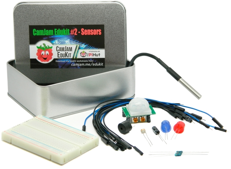
Contents of CamJam EduKit 2

CamJam EduKit 2 small

You will need to provide:

  • A Raspberry Pi (any version, including the Pi Zero) SD card and power supply.
  • A keyboard and mouse. (Pi Zero may require a USB hub and/or adapter)

Buy CamJam EduKit 2 – Sensors

CamJam EduKit 2 is available to purchase from The Pi Hut.

Worksheets

The CamJam EduKit worksheets use the Python 3 programming language with the GPIO Zero library, which is pre-installed on the Raspberry Pi Operating System available from raspberrypi.org.

These worksheets are suitable for use with all of the Raspberry Pi microcomputers. Please make sure to read the instructions carefully for any notes relevant to your particular model.

The components can also be used with microcontrollers, including the Raspberry Pi Pico, although we do not have worksheets written specifically for them.

We also have some partially-complete scripts for Scratch available.

Download everything

You can download all the worksheets and all the code from GitHub by using the following command on the Raspberry Pi:

git clone https://github.com/CamJam-EduKit/EduKit2

Licence

All CamJam EduKit worksheets are covered by a Creative Commons licence. CC-BY-NC-SA

The original Word document versions are available for re-use or translation by contacting us.

Mailing List

Please sign up to our mailing list to get notifications of new and updated worksheets as well as advanced notice of new EduKits.

87 thoughts on “CamJam EduKit 2 – Sensors

  1. Worksheet 2 has an error. The wiring diagram for the buzzer and LED circuit to the GPIO. It shows a brown wire going from the 15RXD to the red led anode, whereas the connection should be to the next pin along, Pin 18….

  2. Is there something else wrong? The words say to connect the grey jumper (black and white in the diagram?) “from the seventh pin from the left on the top row” (which is Gnd) to the top row of the breadboard (positive) but the diagram shows it going from the fifth on the bottom row (which is Gnd). Surely it must connect with a positive somewhere. A general point is the the diagrams are far too small and one cannot easily see the pin legends on the Pi.

    1. You either need to correct the written words “seventh pin from the left on the top row” – where the diagram shows 5th pin on bottom row of pii; OR you need to change wording to “5th pin from the left on the bottom row”.

      I also note that the LEDs will be plugged in the wrong way round as currently guided; the long leg should be on the LEFT not the right.

      As an improvement; I would also suggest that the user is advised to ensure that they start with the breadboard oriented correctly (as I made the mistake of having red positive uppermost and was confused when I noted that it was taking a GND feed) – so I had to restart my circuit for ease of following instructions(having rotated the bread board 180 degrees); it also helped me realise that the polarity was wrong into the LEDS aka the LEFT/RIGHT long leg correction I made above.

      Surprised that this wasn’t picked up when you checked the worksheets…..?

  3. Worksheet 3
    we have completed all coding but without any joy and feel that it is missing a section similar to worksheet 2 whereby it tells the GPIO pins something is attached.

    Maybe we are wrong and you can help with our error code which seems to be an issue with the section ls -l our total =0. We assume this should have some device listed. We have fully updated and upgraded before working through the worksheets so any other suggestions are much appreciated.

  4. Just received my kit. First two exercises OK except for the fact that from the first illustration to the second of the breadboard it has been rotated. Not easy to spot and makes it slightly harder to put all the anodes and cathodes in correctly.
    Number 3 has problems. The cat w1_slave command does not work. Opening the file with nano w1_slave had the lines indicated in the worksheet. Warming the probe and rerunning nano w1_slve showed an increased temperature. So happy there.
    The coding worked all right except for the difficulty that every single variable needed the underscores adding to them. All of them are missing from the downloaded page.

    1. Thanks Robert. We appreciate the feedback. We’re just in the process of updating the worksheets along the lines you’ve mentioned and will be uploading the new ones within the next few minutes.

    1. Sorry for the delay in replying!

      The code is correct – but you may find you have problems if you copy the code from the worksheet due to the way PDF readers layout text. Therefore, type it in.

      Tim

  5. Hi Guys
    Great kits have you thought of any more kits to create. Maybe a more advanced kit and maybe more worksheets with existing and new kit.
    BW Mike

  6. I’ve just tried getting my PIR sensor working following the worksheet and it was just hanging at the waiting to settle print message. I checked my wiring and it appears that I had vcc and ground wired the wrong way. It tried rewiring it the correct way but it still didn’t get past the stage.

    Will I have killed my sensor by wiring the 5v to the gnd pin and if not is there any way I can check that it is working correctly?

    1. I must admit, I’ve not tried to wire mine incorrectly to test it 😉

      However, your issue may well be to do with the device tuning. You should be able to see two potentiometers on the side of the device. Follow the instructions in the Parts section for advice how to adjust them.

      Tim

  7. Hi! I have a problem with worksheet 3. I get an error that I can’t solve.

    Traceback (most recent call last):
    File “3-temperature.py”, line 12, in
    device_folder = glob.glob(base_dir + ’28*’)[0]
    IndexError: list index out of range

    Does anyone know what is wrong?
    /Patrick

    1. This is most likely because the 1-wire protocol has not been set up correctly or is not working. Please go over the ‘Configuring the Raspberry Pi’ in the worksheet one more time.

    2. I got that also and when I checked my code found I’d missed the leading / from the value assigned to base_dir I’d typed:

      base_dir = ‘sys/bus/w1/devices/’

      instead of

      base_dir = ‘/sys/bus/w1/devices/’

      Fixing that was all it took to get it working for me.

    1. Hi Daniel,
      Apologies for the delay. Yes, that’s absolutely fine to alter the worksheets to use Scratch instead. We’re happy to let you have the masters. All we ask is that you send your versions back to us so we can publish them on this site 🙂

      Mike

  8. Hi, I have the following error;

    File “3-temperature.py”, line 42
    return temp_c, temp_f
    SyntaxError: ‘return’ outside function

    Any help for a newbie would be much appreciated.

    Thanks in advance.

    Stuart

    1. Hi Stuart,
      I can’t remember if I replied to this or not – your indentation is wrong in your code. Ensure that the return is indented to the same amount as on the worksheet. NB Cutting-and-pasting from the PDF worksheet doesn’t work very well as it strips out the indents.

  9. Hi, I’m having a problem with worksheet 3. I’ve copied the code out and checked it several times as well as checking the circuit an dI’m certain I’ve followed the instructions however when I run the program it doesn’t do anything – no reports of any errors, it seems to be doing something just not returning anything to the screen.

    I followed the instructions on configuring the Raspberry Pi and the sensor returns a temperature that changes in reaction to heat but the actual program doesn’t seem to work for me????

    Any suggestions please????

    Thank you 🙂

  10. I’m trying to do worksheet three but keep getting this error message:
    File “3-temperature.py”, line 36
    return temp_c, temp_f
    SyntaxError: ‘return’ outside function
    I have been through it all but can’t find the problem typing errors. I typed it as shown on the worksheet.
    I have enjoyed the other projects I’ve done.
    Thank you.

    1. The code _does_ work, but sometimes PIR sensors in general need some adjustment. Take a look at the section that deals with adjusting the sensor. Let me know if you still have problems after you’ve adjusted it.

      1. I had the same problem as Richard and others. The problem was that I built the circuit based on the diagram (I’m better with pictures) which shows the sensor out connected to pin 11. Once I read the code and the text I saw that it should be connected to pin 17. Once I connected it to pin 17, the code gets as far as “Ready” but then doesn’t detect movement.

        Where can I find the instructions on how to adjust the sensor?

        1. Hi – I see your problem. You ARE connecting it to pin 17 – that is the BCM number. It’s the 11th pin (counting from left to right from the top left). Are you sure you have the line ‘GPIO.setmode(GPIO.BCM)’ in your code?

          1. Hi Tim,

            Thanks for this. I had got my head round that eventually. I do have the BCM code in my script. The script is 5-pir.py from worksheet 5. Because I’m running this on an OSMC box it was suggested that I remove the line

            dtoverlay=lirc-rpi:gpio_out_pin=17,gpio_in_pin=18

            which I did, and ensured that the line requested in the worksheets

            dtoverlay=w1-gpi,gpiopin=4

            was included.

            I also tried using a different pin (37, BCM26) and updated to code but had no success.

            Anyone got any ideas please?

  11. Hello. I am having problems with the PIR sensor. It won’t get beyond waiting for PIR to settle. I have adjusted the potentiometers, which aren’t marked by the way, in every combination I can. I have checked the code and wiring and all seems OK there. Thanks

    1. As per Michael Hornes e-mail I went through the code and rewired the PIR but I’m still getting ‘waiting for sensor to settle’. I again tried every combination of adjustments on the potentiometers.

      1. I have started again, with a different Pi2 board, a clean Jesse install post update/upgrade, and re-wired everything as described.

        I’m still sat with “Waiting for PIR to settle …”

        With the sensor facing me and the wires at the bottom, as per in the image I have the left pin connected to pin2 (5v) on the Pi. I have the middle wire connected to pin 11 (GP17) and I have the right pin connected to pin 9 GND on the Pi.

        I have configured /boot/config.txt correctly (minus the spelling mistake) and rum 5-pir.py

        1. I’ve purchased another pi (why not), and another CamJam kit. I’ve set it up exactly as before and now I get different behaviour. Sometimes when I run it, I get as before.

          Sometimes, when I adjust the sensitivity POT I get a different outcome (I’m guessing that the timer as far anti-clockwise as possible is the shortest timespan)

          I’ve added time stamps immediately before each display. As you can see, the sensor settles down quickly and them immediately detects movement – even when there is none
          As soon as it returns to Ready, it detects movement again – even when there isn’t any.

          Any ideas?

          pi@gps1:~ $ python 5-pir.py
          PIR Module Test (CTRL-C to exit)
          21:30:54.056748
          Waiting for PIR to settle …
          21:30:58.675532
          Ready
          21:30:58.686096
          Motion detected!
          21:32:38.875739
          Ready
          21:32:38.886224
          Motion detected!
          ^C Quit
          pi@gps1:~ $

    1. You beat me to it Gary. I found a web site that actually showed a photograph of the module wired up. As you say, the red and black are the opposite of what is shown in the diagram.

      The diagram shows the PIR module facing up with the red wire uppermost. If you wire up the module with the pins facing you, then red is uppermost.

      Once I changed them, the sensor worked perfectly

      1. I had a similar “PIR Waiting” issue due to my GND and VCC wires being the wrong way. I swapped them and it works fine. I also discovered you can remove the white plastic dome and the leads are labelled on the exposed circuit board below. The plastic lids fits back on easy enough.

  12. I have the Raspberry Pi 2 model B and the CamJam edu kit 2. I have worked my way through the worksheets and have got stuck on the PIR sensor. The code sits at Ready but does not detect motion, i have tried to adjust as much as possible with the Sx and Tx as well as switching the Pins about but still the same message of Ready but nothing more. Any help?

      1. So has there been a fix to this? there seems to be a lot of confusion as to which way round the PIR is supposed to be and which rail the +- should link. The PIR I have has no, zippo, nadda help as to which way round it should be as there are no prints on the PCB.

        As a newbie to this I want to throw the whole lot back in the tin and the deposit it in the bin. I was told this was the easy way to get into physical coding, not from my point of view, I feel like I have just wasted the last three hours of my life

        1. Hi Claire,
          Sorry to hear you’re having frustrations with the kit. Could you do us a favour and take photos of the circuit board so we can compare it to the ones we’ve got? We should be able to figure out which potentiometer does what.

          Hope that’s okay.

          Mike

          1. Hi, I have taken some pics but am unsure on hot to attach them to this thread.

  13. Worksheet 2: syntax is wrong in “Code” section (p4 of PDF): [print “Lights and sound on”] -missing brackets
    It’s correct below in the “How the Code works” section.
    Had me stumped for a while, you might want to fix this in the next revision 🙂

  14. As I’ve already stated, I’m looking to deploy these kits around my home, piggy backed on to Pi’s already installed for the LMS music centre project. However my electronics knowledge is very poor – which is partly why I bought my first one of these kits. Can anyone give me the benefit of their thoughts.

    The sensors have:

    PIR – 5v, GND, and OUT
    Light – 3.3v, GND and OUT
    Temp – 3.3v, GND, and OUT
    Buzzer – INPUT and GND

    Is there a problem if I connect all 4 GND pins together. Are all the GND pins on the Pi connected together anyway? Will this for example affect the readings on the LDR?
    Is there a problem if I use only 1 3v3 pin for both the light and temp? Again, if I used say pin 1 and pin 17 is that any difference to the Pi over only using pin 1?

    The only multi-core cable I have is CAT5.
    As all of these are low power is there any problem using a length of CAT5 cable for this project?
    Would the length of the wire affect things. For example if I pit the Pi on the floor behind a cupboard, but put the sensors on the top shelf, would that be okay?

    As you can tell, my electrical knowledge is very minimal

    One thing I will say is that having looked at this kit, and tried to boy the contents the price of £7 is excellent value for money

    1. Hi Gary,
      The ground pins _should_ all be connected together. All the ground pins on the Pi are connected together anyway. This should in no way affect readings.
      It doesn’t matter if you use the same 3.3v pin as they all come from the same place anyway.
      Not sure about the CAT5 cable as we’ve not tried it. But, essentially, if the wire is decent enough quality it should work. Distance _will_ degrade the signal slightly, but a short distance like from the floor to a shelf should be fine. 🙂

      Glad you’re enjoying the kit!

      Mike

  15. Hello,

    I cannot get the temperature sensor to be listed in /sys/bus/w1/devices using the instructions in the PDF. I am using the newest RPi 2 Model B. I’ve added dtoverlay=w1-gpio and even dtoverlay=w1-gpio,gpiopin=4 but still no luck, any suggestions?

    Kevin

    1. I’ve had the same issue as Kevin – I am using an RPi3 but cannot get it to see the temperature sensor. It isn’t listed in /sys/bus/w1/devices. I have followed the instructions in the pdf closely and also tried dtoverlay=w1-gpio (as per Worksheet 3) and dtoverlay=w1-gpio,gpiopin=4 (as per Worksheet 1) but neither seem to work. I’m pretty sure the wiring is correct.

      Are there any differences with the RPi3 that I should be taking into account?
      George

        1. I have the same problem as Kevin and George. I am using a 3. Did you find any solution to this please? I have checked and rechecked all my connections etc.

  16. Worksheet 5&6 PIR Sensor pins – which is which?

    Difficult to sort out what’s what on the PIR sensor – no VCC/GND or other markings on the PIR board, no helpful red/black wires attached, diagram only shows top view of PIR. Most likely conclusion from the diagram is that Left pin is VCC 5V, and Right pin is GND.

    Mr Google was helpful in finding a photo of a marked PIR board, and identifying which potentiometer is Tx and which Sx
    [ http://www.raspberrypi-spy.co.uk/2013/01/cheap-pir-sensors-and-the-raspberry-pi-part-1/ ]

    BUT Raspberrypi Spy has the Right pin as VCC 5V, and the Left as GND.

    So I changed the set up to the Raspberrypi Spy one, and worked thhrough the combinations of potentometer settings – Tx full anti clockwise, Sx halfway; Tx halfway, Sx halfway; Tx full clockwise Sx halfway etc etc etc . Bingo! one worked [ with me Tx full anticlockwise, Sx halfway]

    And I am almost at the end of my tinkering with the Kit1 and Kit2 tins – hard work at times, but great fun.

    Help please – Kit3, the robot car, is out of stock – When will it be back in stock?

    1. Hi Neil,
      Glad you solved the problems. I’m going to be looking at the kit as it currently stands to see what PIR sensor the factory is using. The sensor _should_ have red and black wires, but it sounds like they’ve changed it or something.

      Kit 3 – we currently have some on order and we’re expecting them in the next month.

      Mike

  17. The worksheets are helpful (Even if you dont have the exact kits..) so thanks for that, however, a proper circuit diagram on the worksheets would help greatly (the LDR/light worksheet in particular).

  18. Hi really enjoying these kits.

    The PDF for CamJam EduKit 2 Worksheet 4 reads:

    while True:
    print ReadLDR()

    But should read as the code:

    while True:
    print (ReadLDR())

    This is why I think some people might be having problems.

  19. I have found the wires on the temperature sensor far too short, only 5mm, and I have no access to a soldering iron. Do you have any suggestions?

  20. Hi. Struggling with Worksheet 3! (Two worked fine). I’m new to Unix so may have made mistakes but have tried to follow code exactly.
    Typed in the sudo stuff and rebooted. But when I ‘ls’ the /sys/bus/w1/devices directory there is no “28xxx” there.
    Do I just re-type the code before, or is there a way to know what is wrong?

    1. Have you checked the breadboard and that all the wires are positioned correctly. I had this problem but it was just that the wires were not correctly positioned

  21. I’m having the same problem on my Pi3 running pixel. There is nothing called 28-000* in the /sys/bus/w1/devices folder. I’ve tried various config.txt options, including using the built in pullup (for which i removed the pull up resistor) and I’ve rebuilt the circuit multiple times to be sure I got it right. Interestingly it did work to begin with. I think it may have stopped working when I did either a apt-get update or a dist-upgrade. I’m going to try it on my pi B when I get a chance but there does seem to be a number of people with issues reading gpio after doing updates.

  22. My son and I are having an issue with the temperature sensor. We did manage to get the sensor installed and do get an output, but this is all the time 0.0, 32.0 (thus 0 celsius, 32 fahrenheit). It is not that cold in his room ;-). I am pretty sure that the wiring is correct, although the wires on the sensor were difficult to put in the breadboard, even after having them stripped.

  23. Hi trying to get the PIR senor working. Have the code exactly the same as the worksheet the only change is that i have swapped the 5v and the ground wires as per instructions further on the comments and other online tutorials. It runs fine and then says ready however motion is not registered. Any ideas ?

  24. Hi
    Do you have the answers to the Challenges anywhere please? I’m new to python and trying to figure out with my son how to make the lights/buzzer light up when the temp sensor reaches a given temperature. We’ve figured out that we need an IF statement and how to write one – but can’t work out what variable to refer to in checking whether the reading is >0.5 degrees. I’d thought it was temp_c but I gather that isn’t defined…and my lack of knowledge will become worse on the harder challenges!
    thanks

      1. I, too, am in Catherine’s boat. Tried looking at glob in the library and still haven’t pieced together yet. Was hoping to find a recipe for a temperature sensor that also had an LED, but haven’t yet. Thanks

  25. Hi, I’m a bit stuck with Worksheet 3, The code seems to run fine and i’m pretty sure that my wiring is correct as well but when i run it, it just says ‘None’ repeatedly each second. Any Idea about how i can fix it?

    1. Hi Iwan, I had the same issue. When I checked the code again, I had a type in the line that reads “equals_pos = lines[1].find)’t=’)”
      I had typed a “+” instead of the “=” at the end.
      Hope this helps.

  26. Hi, I am having an issue with Worksheet 6 – Sensors. I’ve set up the breadboard and pi as shown in the picture, and even copied the code directly from the pdf, but I always get and invalid syntax error. I am running the code in Python 3 (IDLE), and I still get the error. I don’t think there is an all out fix for this, but if anyone has an answer or helpful response, please reply!

  27. Sorry, I know this has been discussed a few times before but I still can’t find an answer. I have a 3 and am trying to get the project 3 – Temperature to work. I have wired up the circuit and checked it lots of times. I have checked that the dtoverlay line is in config.txt. But when I run the 4 lines of configuration in the Terminal window, the list command returns no devices, as others have found. Also after entering all the code to run the 3-temperature.py programme, I get the message ‘invalid syntax’ despite having checked the coding a number of times. (Maybe the two issues are related?). As a newbie to the RPi this is a bit frustrating as I don’t have the knowledge to sort the problem out. Can anyone help pls?

    1. OK, I think I have found a part solution to my problem. In the config.txt file in the dtoverlay line I had put a space between dtoverlay=w1-gpio and ,gpiopin=4. By removing the space I was able to run the 4 lines of configuration and get the data for the sensor device. In the CamJam instructions it looks like there IS a space in the line of coding but this highlights for me a problem reading printed coding where it is often not clear what is and is not a space between bits of code. My other problem of the ‘invalid syntax’ when running the 3-temperature.py programme remains.

      1. For my Raspberry Pi 3 I discovered that I had to type cd /sys/bus/w1/devices/w1_bus_master1 , then return. If you type this command then type ls, you should see the 28-xxxx number, provided that the probe is hooked up correctly. You will need to type in the CD 28-xxxx command and the cat w1_slave also.
        In the program itself, you will need to modify the code for base_dir to = ‘ /sys/bus/w1/devices/w1_slave/w1_bus_master1/’
        The code worked fine after this. This fix worked for all of my students also – all were able to get their temperature sensors working with the code.

Leave a Reply

This site uses Akismet to reduce spam. Learn how your comment data is processed.